As the NM is a synchronous register-transfer level (RTL) architecture, the NM/DBN systems can be implemented only using a few types of hardware components such as shift registers, arithmetic operators, and memories. Therefore, an accurate and efficient hardware simulation of the system can be coded in a conventional programming language, as implemented here.
The hardware simulator is a program that runs on the MathWorks MATLAB environment without requiring additional files. It is designed in a layered architecture. At the botton, hardware components such as pipeline registers and pipelined arithmatic operators are simulated. Upon the hardware simulation layer, the circuit of the hardware system, our NM system, is implemented. The implemented system simulates a DBN neural network and the simulation resultes are displayed on the screen.
Our hardware simulator code is structured as following.
   Initialization part;
   ...

   for ck = 1:1E9   % Clock loop

      Circuit description;
      ...

      % shifting pipeline registers
      R(:,2:8) = R(:,1:7);  R(:,1) = 0;
      % shifting pipelined arithmetic operators
      C(:,2:8) = C(:,1:7);  C(:,1) = 0;
   end
This code is composed of two parts. The first part is the initialization part (lines 1-3), which shows how the contents of the memories and control registers are stored. The rest of the code, the clock loop, is for executing the simulation. The variable ck in the loop represents the system clock cycle, and each ck loop simulates a single clock cycle. The vector R is used for registers, and C is used for arithmetic operators. At the end of the clock loop, the registers and pipelined operators are shifted one step forward. The code has properties similar to hardware description languages.
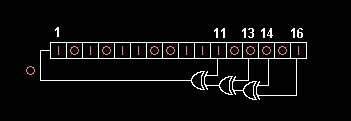
As a simple example, consider a Fibonacci LFSR pseodo random number generator, as shown below.
This circuit can be translated into hardware simulator as following.
R = zeros(10,50);
R(1,10) = 1; % set initial state

for ck = 1:1E9   % Clock loop

  % implementation
  R(1,1)=xor(R(1,12),xor(R(1,14),xor(R(1,15),R(1,17))));

  % shifting pipeline registers
  R(:,2:50) = R(:,1:49); R(:,1) = 0;
end
Sample lines of our simulator code can be interpreted as:
- C(2,1) = R(10,2) + R(4,2); : Adder C2 has two inputs connected from the outputs of registers R10 and R4.
- R(11,1) = C(2,7); : The output of operator C2 is connected to register R11. C2 has a pipeline delay of 6 (from 1 to 7).
- R(1,1) = MemW(Caddr(1)); : The output of memory MemW is connected to register 1. MemW is addressed by a pipeline register Caddr(1).
- Mem_Mx(Caddr(22)) = R(7,2); : The output of R7 is connected to the write port of memory MemW.
- if R(2,2) R(3,1) = R(1,2); else R(3,1) = 0; end; : Multiplexer controlled by the output of register 2. Depending on the value of R2, the outputs of R1 or the value zero are selected and assigned to R3.
