Following figure is a full circuit diagram of our system.
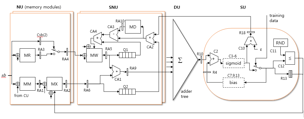
Full circuit diagram of the system (except control unit)
Network Unit (NU)
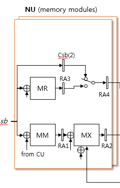
Circuit of Network Unit. There are a total of 64 memory modules in the NU. A 1-bit memory called numm memory (MN) is not shown here.
    % Network Unit

    % note: tsb(n) denotes pipeline timing ralative to sb signal (sb=1)
    RA(3,1,:)  = MR(sb + currSOT(9) + 1, : ); % tsb(1)
    RA(1,1,:)  = MM(sb + currSOT(6) + 1, : ); % tsb(1)
    RA(13,1,:) = MN(sb + currSOT(6) + 1, : ); % tsb(1)
    for k = 1:64
      RA(2,1,k)  = MX(RA(1,2,k) + currSOT(7) + 1, k); % tsb(2)
    end
    RA(2,1,(RA(13,2,:)>0)) = 0; % clear null synapses
    % MW address selection
    if sType==3                         % tsb(2)
      RA(4,1,:) = RA(3,2,:);  % output of MR if reverse stage (stage 3)
    else
      RA(4,1,:) = Csb(2);     % forward stage
    end;
Synapse Unit (SNU)
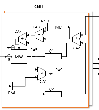
Circuit for Synapse Unit. There are a total of 64 SNUs in the system.
    % Synapse Unit

    if sType==3                                 % tsb(3)
      RA(6,1,: ) = mod(hex2dec(num2hex(single(RA(2,2,: )))),2);
    else
      RA(6,1,:) = RA(2,2,: );
    end
    for k = 1:64
      RA(5,1,k) = MW(RA(4,2,k) + currSOT(10) + 1, k); % tsb(3)
    end;
    CA(1,1,:) = RA(5,2,: ) .* RA(6,2,: );         % tsb(4)
    RA(12,1,:) = CA(1,7,: );                     % synapse output, tsb(10)
    Q(1,mod(ck + 130, 200) + 1,: ) = RA(5,2,: );  % weight is queued, tsb(4)
    Q(2,mod(ck + 117, 200) + 1,: ) = RA(6,2,: );	% synaptic input is queued, tsb(4)
    CA(2,1,: ) = Q(2,mod(ck,200)+1,: ) .* R(18,2);% vpos*hpos or vneg*hneg, tsb(121)
    if sType==2 && Csben(127)                   % tsb(127)
      % save to MD when vpos*hpos
      MD(Csb(127) + 1, : ) = CA(2,7,: );  % note: no offset for MD
    else
      % read from MD
      RA(10,1,: ) = MD(Csb(127) + 1, : );
    end;
    % following lines are effective only when stage type = 4
    RA(9,1,: ) = CA(2,7,: );                        % vneg*hneg, tsb(127)
    CA(3,1,: ) = RA(10,2,: ) - RA(9,2,: );           % compute delta w, tsb(128)
    CA(4,1,: ) = Q(1,mod(ck,200)+1,: ) + CA(3,7,: ); % compute new weight, tsb(134)
    if sType==4 && Csben(140)                     % update MW, tsb(140)
      MW(Csb(140) + currSOT(10) + 1,: ) = CA(4,7,: );
    end;
    if Csben(140) && Csb(140)==currSOT(4)-1       % last pipeline point, tsb(140)
      eos = 1;
    end
Dendrite Unit (DU)
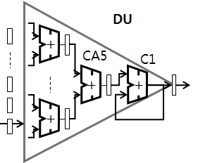
Circuit of Dendrite Unit. There are 63 pipelined adders and one accumulator (C1).
  % Dendrite Unit (adder tree)

  % first adder stage
  CA(5,1,32:63) = RA(12,2,(1:32) * 2 - 1) + RA(12,2,(1:32) * 2);
  % rest of adder stages
  CA(5,1,1:31) = CA(5,7,(1:31) * 2) + CA(5,7,(1:31) * 2 + 1);
  % accumulator
  C(1,1) = CA(5,7,1) + C(1,2) * (mod(Csb(47),currSOT(3))~=0); % tsb(47)
  RL(3,1) = C(1,7);                                           % tsb(53)
  tempsig = RL(3, 33 - currSOT(3));  % variable-sized buffer for timimg, tsb(85 - bpn)
  % begining of neuron control signals (following 2 lines are part of CU)
  nren = (Csben(84) && mod(Csb(84),currSOT(3))==0);     % tsb(84), tnr(0)
  nr = nr + (nren && Csb(84)>currSOT(3)-1);
  if nren
    % netsum stays valid until the next one
    net_sum = tempsig;      % tsb(84), tnr(0)
  end;
  R(10,1) = net_sum;        % tsb(84), tnr(0)
Soma Unit (SU)
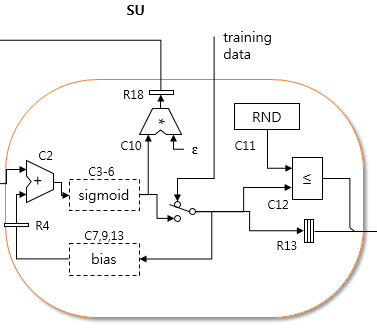
Circuit of Soma Unit

  % Soma Unit

	% note: tnr(n) denotes pipeline timing ralative to nr signal (nr=0)
  % sigmoid = 1 / (1 + exp(-netsum))
  C(2,1) = R(10,2) + R(4,2);    % add offset to the netsum, tsb(85), tnr(1)
  C(3,1) = -1 * C(2,7);         % -netsum, tsb(91), tnr(7)
  C(4,1) = exp(C(3,7));         % exp(-netsum), tsb(97), tnr(13)
  C(5,1) = C(4,7) + 1;          % 1 + exp(-netsum), tsb(103), tnr(19)
  C(6,1) = 1 / C(5,7);          % prob = 1 / (1+exp(-netsum)), tsb(109), tnr(25)
  C(10,1) = ew * C(6,7);        % epsilon * prob, tsb(115), tnr(31)
  R(18,1) = C(10,6);            % tsb(120)
  R(4,1) = MB(nr + currSOT(11) + 1); % read MB for bias, tnr(0)
  RL(1,1) = R(4,2);             % bias is queued in a long fifo, tnr(1)

  % MA write
  if sType==2     % write once, read twice (for current and next RBM), tnr(31)
    R(7,1) = Cnren(31);
    R(6,1) = Cnr(31) + currSOT(12);
    R(8,1) = C(6,7);
  end

  % update bias
  if sType==3 || sType==4
    R(11,1) = C(6,7);                   % current prob, tnr(31)
    R(5,1) = MA(Cnr(31) + currSOT(12) + 1);  % and stored prob, tnr(31)
    C(7,1) = R(5,2) - R(11,2);          % compute difference, tnr(32)
    if sType==3 && Cnren(33)            % squre error of visible layer, tnr(32)
      er = er + (R(5,2) - R(11,2))^2;
    end;
    C(13,1) = C(7,7) * eb;              % delta bias, tnr(38)
    C(9,1) = RL(1,44) + C(13,7);        % add old bias with delta for new bias, tnr(44)
    if Cnren(50)                        % tnr(50)
      MB(Cnr(50) + currSOT(11) + 1) = C(9,7);  % save bias
    end;
  end